
Wire Rope Clip Installation That Holds Under Load
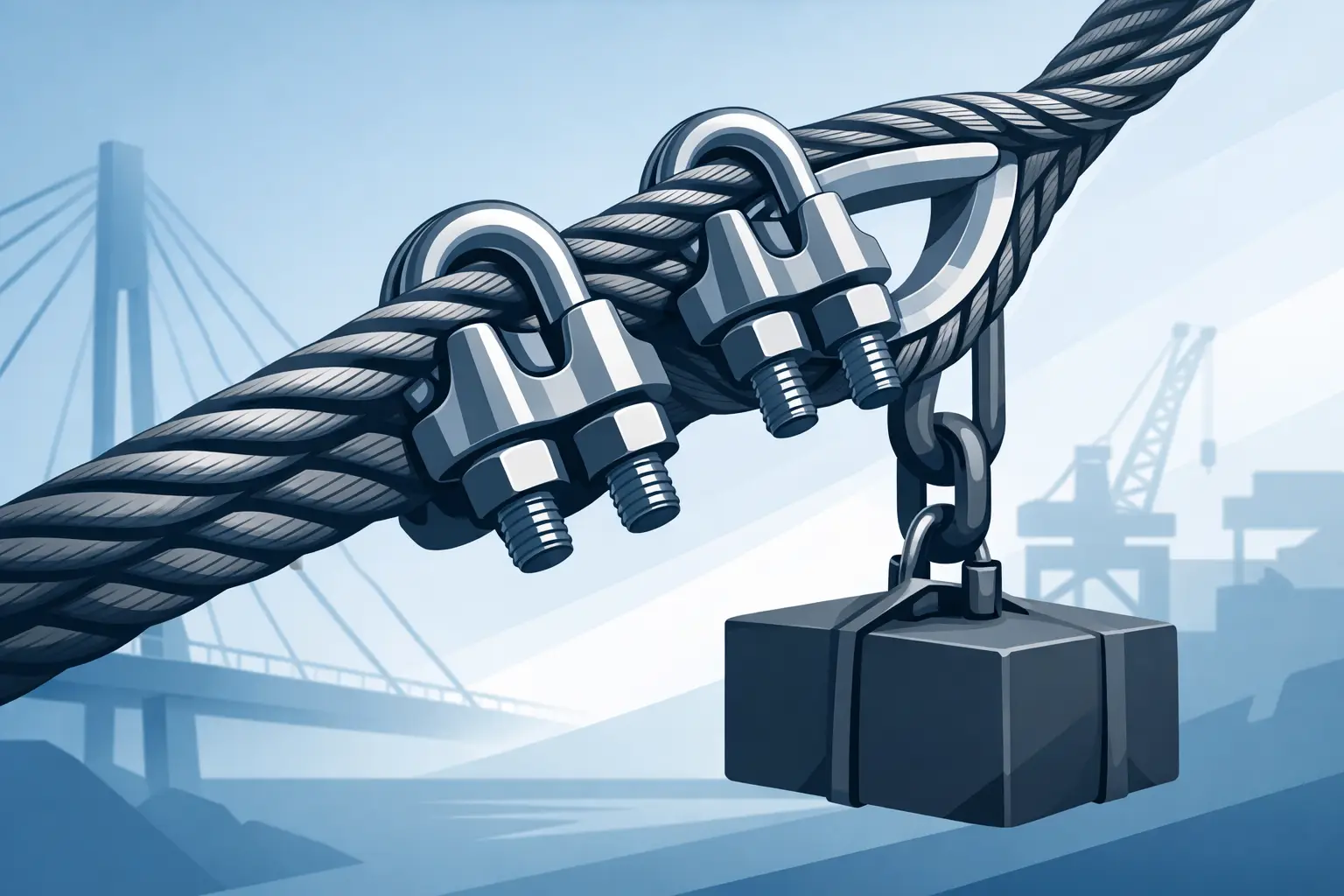
A wire rope termination is only as dependable as the hardware, installation method, and inspection behind it. Correct wire rope clip installation prevents a temporary eye from becoming a dropped-load incident, damaged equipment, or an unplanned shutdown. For field-made eyes, clips can provide a practical, serviceable termination – but only when the rope, clips, spacing, torque, and application are properly matched.
Start With the Right Clip and Rope
Wire rope clips are not universal hardware. Select clips specifically rated for the rope diameter, rope construction, and intended service. Never assume a clip that physically fits is suitable for the job. The manufacturer’s catalog data should identify the wire rope diameter range, required number of clips, minimum turnback length, clip spacing, and nut torque.
Match the clip type to the application. Standard U-bolt clips are common for general-purpose wire rope eyes and guy-line assemblies. Fist grip clips use two saddles and are often preferred where the installation needs a more balanced grip or where the risk of installing a U-bolt backward is a concern. Forged clips are generally specified for demanding industrial service; malleable cast clips may be limited to lighter-duty applications depending on manufacturer guidance and site requirements.
Do not mix clip brands, sizes, or hardware grades in one termination. The clip assembly works as a system, and substituting nuts, saddles, or U-bolts can change its holding performance. Use only genuine, correctly marked components with traceable load information when the connection supports operationally critical equipment.
Before assembly, inspect the rope. Reject rope with severe corrosion, broken wires, crushing, kinks, birdcaging, heat damage, or evidence of shock loading. A new clip installation cannot restore the capacity of a damaged rope.
Wire Rope Clip Installation: The Correct Orientation
The most common and most preventable error is placing the U-bolt on the live end of the wire rope. The live end is the load-bearing section that continues into the working line. The dead end is the short turnback end after the eye has been formed.
For U-bolt style clips, place the saddle on the live end and the U-bolt over the dead end. Field crews often remember this as: never saddle a dead horse. The phrase is simple, but the reason matters. The U-bolt concentrates pressure and can damage the load-bearing section of the rope if installed on the live end.
Form the eye around a correctly sized thimble where abrasion, bending, or repeated connection to a shackle, hook, or link is expected. A thimble protects the rope at the eye and helps maintain the proper bend radius. Select a thimble sized for both the wire rope and the connecting hardware. An undersized thimble or oversized shackle pin can create unfavorable bending and shorten rope service life.
Place the first clip immediately next to the thimble, with the saddle on the live end. Do not position it so tightly that the thimble is distorted or the rope is pinched into an irregular shape. Install the remaining clips at equal spacing along the turnback length, following the clip manufacturer’s specified dimensions.
Number of Clips, Spacing, and Turnback Length
There is no safe rule of thumb that replaces the manufacturer’s installation table. Required clip count increases with rope diameter, and required spacing changes by clip model and rope size. Installing too few clips, reducing the required turnback, or crowding the clips together can reduce holding strength and allow the rope to slip under load.
As a practical check, the clips should be evenly spaced, aligned, and installed on a straight section of rope. Do not stack clips together near the thimble to make the assembly look compact. The termination needs the specified turnback length to distribute gripping force over the rope.
For critical work, the rigging supervisor should verify the clip count and spacing against the product documentation before the assembly is placed in service. This check takes minutes and is far less costly than investigating a failed connection.
Tighten to the Specified Torque
Install the nuts evenly and tighten them to the manufacturer’s recommended torque using a calibrated torque wrench. Tightening by feel is not adequate for load-bearing wire rope terminations. Under-torqued clips can slip. Over-torqued clips can crush the rope, damage strands, and reduce rope performance.
Tighten each clip progressively rather than fully tightening one clip before moving to the next. This helps keep the rope seated correctly and distributes clamp pressure more consistently. Once the final torque is reached, inspect the assembly for a properly seated thimble, correct saddle orientation, straight clip alignment, and an undamaged live end.
A visual mark at the end of the rope near the first clip can help reveal movement during initial loading and later inspections. If the mark moves, remove the assembly from service and determine why the termination is slipping. Do not simply add another clip or apply more torque without identifying the cause.
Retightening Is Part of the Installation
Newly installed clips require follow-up. Wire rope can settle, strands can compact, and hardware can lose preload after the first loading cycle. Retorque all clip nuts after the assembly has been initially loaded, then inspect and retighten at intervals established by the manufacturer and your site’s rigging inspection program.
This requirement is especially relevant in oilfield, maritime, construction, and heavy-equipment environments where vibration, weather exposure, and repeated loading can affect the termination. A connection that looked correct during installation may change after a shift of service.
Inspection should include clip orientation, nut tightness, rope movement, broken wires near the clips, thimble condition, corrosion, and deformation. Look for flattened or crushed rope beneath the clips, which may indicate excessive torque or an incorrect clip size. Replace compromised components rather than attempting a field repair with mismatched hardware.
Understand Capacity and Application Limits
A wire rope clip termination does not automatically retain the full rated capacity of the original wire rope. Termination efficiency varies by rope type, clip design, installation method, and manufacturer. The allowable working load for the completed assembly must be based on the lowest-rated component and the applicable reduction for the termination.
That means the rope’s nominal strength is not the only number procurement and field teams need. Review the assembled system: wire rope, clips, thimble, shackle or hook, sling angle, and the expected loading condition. Side loading, shock loading, edge contact, and multi-leg configurations can change the actual force applied to the eye.
Wire rope clips are often suitable for static or general-purpose field connections when specified correctly. They may not be appropriate for certain lifting applications, rotating loads, personnel lifting, or high-cycle service. For those applications, a swaged socket, poured socket, or professionally fabricated termination may be the better choice. The right answer depends on the duty cycle, consequence of failure, governing standards, and equipment manufacturer requirements.
Avoid These Field Installation Failures
The most frequent failures are not complicated: the wrong clip size, U-bolt installed on the live end, too few clips, no thimble where one is needed, incorrect spacing, and nuts tightened without a torque reference. Another recurring issue is using clips on a rope that has already been damaged, flattened, or contaminated.
Do not use wire rope clips to join two ropes end to end unless the specific arrangement is engineered and approved for that purpose. Do not install clips over plastic-coated rope unless the manufacturer expressly permits it. The coating can compress and later relax, leaving an unreliable grip.
Avoid making assumptions from a previous job. A 3/8-inch rope, a 1/2-inch rope, and a 5/8-inch rope do not share the same clip requirements. Keep the installation instructions with the rigging documentation, particularly when equipment moves between yards, vessels, or remote field locations.
Build the Check Into the Job Plan
For crews working against a shutdown window or mobilization deadline, clip installation can feel like a minor task. It is not. Treat it as a load-connection task with a documented verification point before service. Confirm rope diameter, clip model, clip quantity, saddle orientation, torque, turnback, and post-load retorque requirements.
Pro Oil Field Supply supports industrial teams with heavy-duty wire rope hardware, lifting components, and specification-focused sourcing for demanding field work. When the application involves a critical load path, choose identified, load-rated hardware and verify the complete assembly before the load ever leaves the ground.
A correctly installed clip assembly does more than hold rope in place. It gives the crew a connection they can inspect, maintain, and trust when uptime and safe handling are on the line.